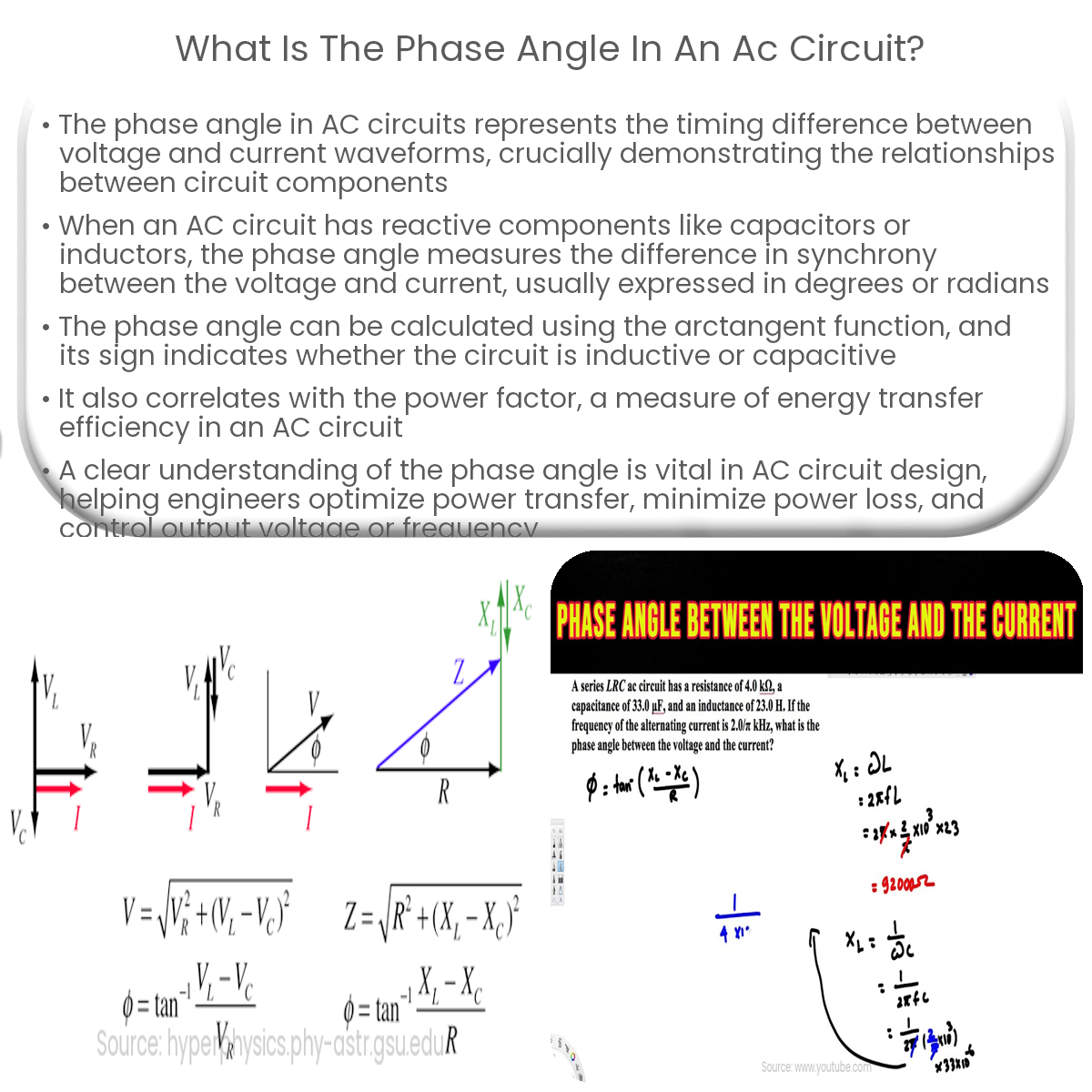
The phase angle in an AC circuit represents the timing difference between voltage and current waveforms, typically caused by reactive components.
Understanding Phase Angle in AC Circuits
In alternating current (AC) circuits, the phase angle is an essential concept that describes the difference in timing between two waveforms, such as voltage and current. It helps to illustrate the relationships between various components in an AC circuit, such as resistors, capacitors, and inductors.
Phase Angle and Reactance
When an AC circuit contains reactive components like capacitors or inductors, the voltage and current waveforms are not perfectly in sync. This occurs due to the storage and release of energy by these components, leading to a phase difference between the voltage and current. The phase angle (θ) is the measure of this difference, typically expressed in degrees or radians.
Calculating the Phase Angle
The phase angle in an AC circuit can be calculated using the arctangent function. For a series RLC circuit, the formula is:
θ = arctan((Xₗ – Xc) / R)
Where θ is the phase angle, Xₗ is the inductive reactance, Xc is the capacitive reactance, and R is the resistance. If Xₗ > Xc, the phase angle is positive, indicating an inductive circuit. Conversely, if Xₗ < Xc, the phase angle is negative, indicating a capacitive circuit.
Power Factor and Phase Angle
The phase angle is related to the power factor, a dimensionless quantity that ranges from -1 to 1. It represents the efficiency of energy transfer in an AC circuit. The power factor (PF) is calculated using the cosine of the phase angle:
PF = cos(θ)
A power factor of 1 signifies a purely resistive circuit, where the voltage and current are perfectly in phase. A power factor of 0 indicates that the circuit is purely reactive, with the voltage and current waveforms being 90 degrees out of phase.
Applications and Significance
Understanding phase angle is crucial in the design and analysis of AC circuits, particularly when working with reactive components. It provides insights into the behavior of circuits with varying load conditions, enabling engineers to optimize power transfer and minimize power loss. Moreover, phase angle control is widely used in power electronics, such as in phase-controlled rectifiers and variable frequency drives, to control the output voltage or frequency.


