A voltage tripler circuit amplifies input AC voltage to approximately three times its initial amplitude using diodes and capacitors for various applications.
Introduction to Voltage Tripler Circuit
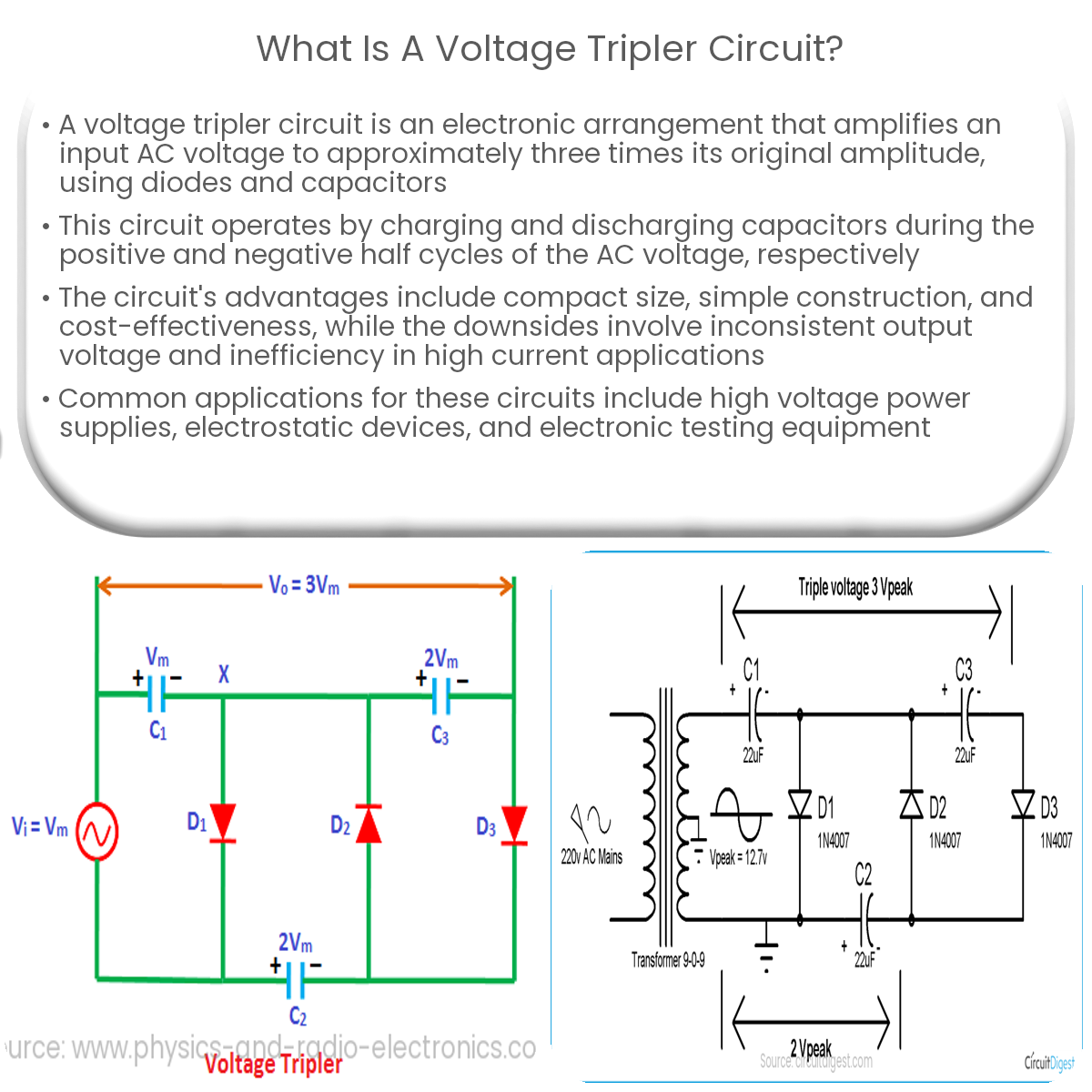
A voltage tripler circuit is an electronic configuration designed to amplify an input alternating current (AC) voltage to a level approximately three times its initial amplitude. The circuit employs diodes and capacitors to create a higher direct current (DC) output voltage. Voltage tripler circuits are commonly found in various applications, such as high voltage power supplies, electrostatic devices, and electronic testing equipment.
Working Principle of Voltage Tripler Circuit
The voltage tripler circuit operates based on the charging and discharging of capacitors, in conjunction with diodes, to control the flow of current. During the positive half cycle of the input AC voltage, a specific arrangement of diodes allows the charging of capacitors, and during the negative half cycle, the stored energy in these capacitors is combined to generate the desired output voltage. The overall process results in a DC output voltage that is approximately three times the peak value of the input AC voltage.
Components of Voltage Tripler Circuit
- Diodes: Diodes are semiconductor devices that permit current flow in only one direction. In a voltage tripler circuit, diodes are crucial for controlling the charging and discharging of capacitors.
- Capacitors: Capacitors are passive electronic components that store electrical energy when subjected to a voltage. They play a vital role in charging and discharging processes in a voltage tripler circuit, enabling the generation of a higher output voltage.
Advantages and Disadvantages of Voltage Tripler Circuit
- Advantages:
- Compact size and simple construction.
- Efficient way to multiply input voltage without using transformers.
- Lower component cost compared to other voltage multiplication techniques.
- Disadvantages:
- Output voltage is not constant and can vary depending on the load conditions.
- Not suitable for high current applications, as the circuit’s efficiency decreases with increasing load current.
- May generate high-frequency noise due to the rapid charging and discharging of capacitors.
Applications of Voltage Tripler Circuit
Voltage tripler circuits are used in a variety of applications that require high voltage outputs. Some common uses include:
- High voltage power supplies for cathode ray tubes (CRTs) and X-ray machines.
- Electrostatic devices, such as air purifiers and electrostatic precipitators.
- Electronic testing equipment requiring high voltage levels.
- Signal generators and waveform synthesizers.