Explore the basics of Resistor-Capacitor (RC) circuits, their components, working principles, applications, and advanced analysis.
Introduction to Resistor-Capacitor (RC) Circuits
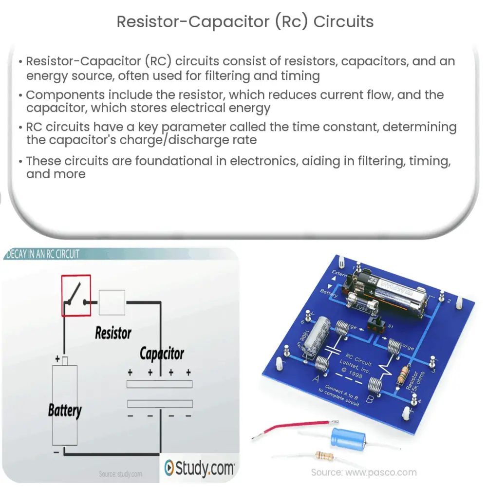
A Resistor-Capacitor (RC) circuit is a type of electric circuit that consists of resistors, capacitors, and an energy source. These simple yet robust circuits are often used in electronics due to their unique properties, especially in filtering and timing applications.
Understanding the Components
- Resistor (R): A passive two-terminal electrical component that implements electrical resistance as a circuit element. It is used to reduce current flow and lower voltage levels within circuits.
- Capacitor (C): Another passive two-terminal electrical component that stores electrical energy in an electric field. The effect of a capacitor is known as capacitance.
Working Principle of RC Circuits
RC circuits can be classified into two main types: series RC circuits and parallel RC circuits. The fundamental principle of an RC circuit revolves around the storage and discharge of energy in the capacitor. When the circuit is powered, the capacitor charges up to the supply voltage through the resistor. This charging process is not instantaneous; it follows an exponential curve based on the time constant (τ), given by the product of resistance (R) and capacitance (C).
Time Constant in RC Circuits
The time constant (τ) is a crucial parameter in RC circuits. It determines the rate at which the capacitor charges or discharges. Mathematically, it is the time taken by the capacitor to charge about 63.2% of the applied voltage when charging, and the time it takes to discharge to 36.8% of its initial charge value during discharging.
Applications of RC Circuits
RC circuits are found in a multitude of applications, thanks to their versatile properties. Some of these applications include:
- Filter Circuits: RC circuits are often used in creating filter circuits. By properly choosing the values of the resistor and capacitor, one can design high-pass or low-pass filters.
- Timing Circuits: The exponential charging and discharging behaviour of the capacitor in an RC circuit can be used to create timers and oscillators. This is especially useful in digital electronics.
These applications highlight the importance of RC circuits in the field of electronics. In the next section, we will delve deeper into the mathematical analysis of RC circuits and explore more advanced topics.
Mathematical Analysis of RC Circuits
By employing Kirchhoff’s laws and the definition of capacitance (Q = CV), the behavior of RC circuits can be modeled with differential equations. In a series RC circuit, for instance, when a voltage V is suddenly applied across the terminals, the voltage across the capacitor (VC) increases according to the equation VC = V(1 – e-t/RC), where e is the base of the natural logarithm (approximately equal to 2.71828), t is the time elapsed since the application of voltage, and RC is the time constant of the circuit.
Transient and Steady-State Analysis
The study of RC circuits often involves understanding the transient and steady-state response. Transient response refers to what happens when a circuit switches from one state to another, while the steady-state response is the behavior of the circuit after a long time has passed. The time constant (τ) plays a pivotal role in both these analyses.
Parallel and Series RC Circuits
The behavior of RC circuits varies depending on whether the resistor and capacitor are connected in series or parallel. In a series RC circuit, the capacitor and resistor share the same current, but voltages may differ. In contrast, in a parallel RC circuit, the voltage across the resistor and capacitor is the same, but the currents may differ. Depending on the configuration, RC circuits can serve different roles in electronic systems.
Complex Impedance and Phasor Analysis
For sinusoidal inputs, RC circuits can be analyzed using complex impedance and phasor analysis. The impedance (Z) of an RC circuit is a complex quantity, given by Z = R + jX, where R is the resistance, j is the imaginary unit, and X is the reactance, which depends on the frequency of the input signal and the capacitance.
Conclusion
In conclusion, Resistor-Capacitor (RC) circuits are fundamental building blocks in electronics. From basic filtering to timing applications, these circuits are versatile and crucial in the design and operation of many electronic systems. By understanding the properties of the components (resistors and capacitors) and the different configurations (series and parallel), along with the principles of time constant, transient and steady-state analysis, and phasor analysis, one can effectively design and utilize RC circuits. As technology advances, RC circuits will continue to play a vital role in the evolution of electronics.


