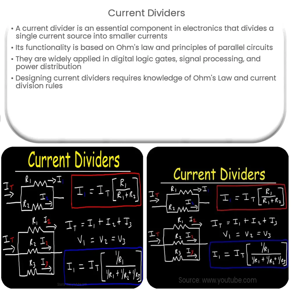
Explore the principles of current dividers in electronics, their real-world applications, and learn how to calculate and design them efficiently.

Introduction to Current Dividers
A current divider is a simple, yet essential component used extensively in the field of electronics and electrical engineering. It is a circuit that divides the total current from a single source into smaller currents flowing through different branches.
Working Principle of Current Dividers
The functionality of current dividers is grounded in Ohm’s law and the principles of parallel circuits. When connected in parallel, resistors share the same voltage, but the current is divided among them based on their respective resistances. The larger the resistor value, the smaller the current it will receive, and vice versa. This division is described by the current division rule, which is essential for understanding the behavior of current in circuits with multiple parallel components.
Applications of Current Dividers
Current dividers have a wide array of practical applications. They are used in the design of electrical circuits where it is necessary to distribute current to various components in a specific proportion. For example, they can be found in digital logic gates, signal processing circuits, and power distribution networks.
- Digital Logic Gates: In digital electronics, current dividers are used to control the flow of current through different branches, thereby affecting the overall output of the logic gate.
- Signal Processing Circuits: In these circuits, current dividers help manage the current flow to ensure the correct functioning of individual components, thereby maintaining signal integrity.
- Power Distribution Networks: In power systems, current dividers ensure that the right amount of current is delivered to various appliances or components of a circuit, thus ensuring safe and efficient power usage.
Calculating Currents in a Current Divider
Calculating the amount of current flowing through each branch in a current divider circuit involves using the current division formula. This formula states that the current flowing through a resistor in a parallel combination is inversely proportional to its resistance. It’s given by In = ITotal * (RTotal/Rn) where:
- In is the current flowing through the nth resistor
- ITotal is the total current supplied to the circuit
- RTotal is the total resistance of the circuit
- Rn is the resistance of the nth resistor
Understanding this formula is key to working with current dividers and manipulating current flows in electronic circuits.
Current Divider Rule for More than Two Resistors
In the case of more than two resistors connected in parallel, the current divider rule can still be applied. However, it becomes a bit more complex as it now involves the sum of the other resistors. The formula for calculating the current through the nth resistor in this case is In = ITotal * (Rsum/Rn), where Rsum is the sum of all other resistances except Rn. With this rule, we can analyze and calculate the currents in more complex parallel circuits with multiple resistors.
Important Considerations for Current Dividers
Despite its simple premise, it’s essential to bear in mind some considerations when working with current dividers. One of the key points is the power ratings of the components. Components in a current divider circuit must have sufficient power ratings to handle the currents that will be flowing through them. If a component’s power rating is exceeded, it can become damaged or even cause the entire circuit to fail.
Designing Current Dividers
Designing a current divider involves understanding the total current that needs to be divided and the desired current in each branch. It also necessitates a good grasp of Ohm’s Law and the current division rule. These considerations dictate the resistances required for each branch. It’s also important to remember that the values of resistors readily available may not exactly match calculated values. As such, you’ll need to select the closest available resistor value that doesn’t exceed the component’s power rating.
Conclusion
In conclusion, a current divider is an essential concept in electronics and electrical engineering that deals with the division of current in parallel circuits. The principles underlying current dividers, such as Ohm’s Law and the current division rule, are fundamental to understanding and designing electrical circuits. Despite its simplicity, the current divider plays a crucial role in a wide array of applications, from digital logic gates to power distribution networks. With the right understanding and application, current dividers can help ensure the proper functioning and efficiency of electronic circuits.


