A center-tapped full-wave rectifier efficiently converts AC to DC, using a center-tapped transformer and two diodes to utilize both halves of the AC waveform.
Center-Tapped Full-Wave Rectifier: An Overview
Introduction
A center-tapped full-wave rectifier is a vital component in the field of power electronics, playing an essential role in converting alternating current (AC) to direct current (DC). This conversion process is known as rectification. A full-wave rectifier allows the utilization of both halves of the AC waveform, making it more efficient than a half-wave rectifier. In this article, we will explore the working principle, construction, and applications of a center-tapped full-wave rectifier.
Working Principle
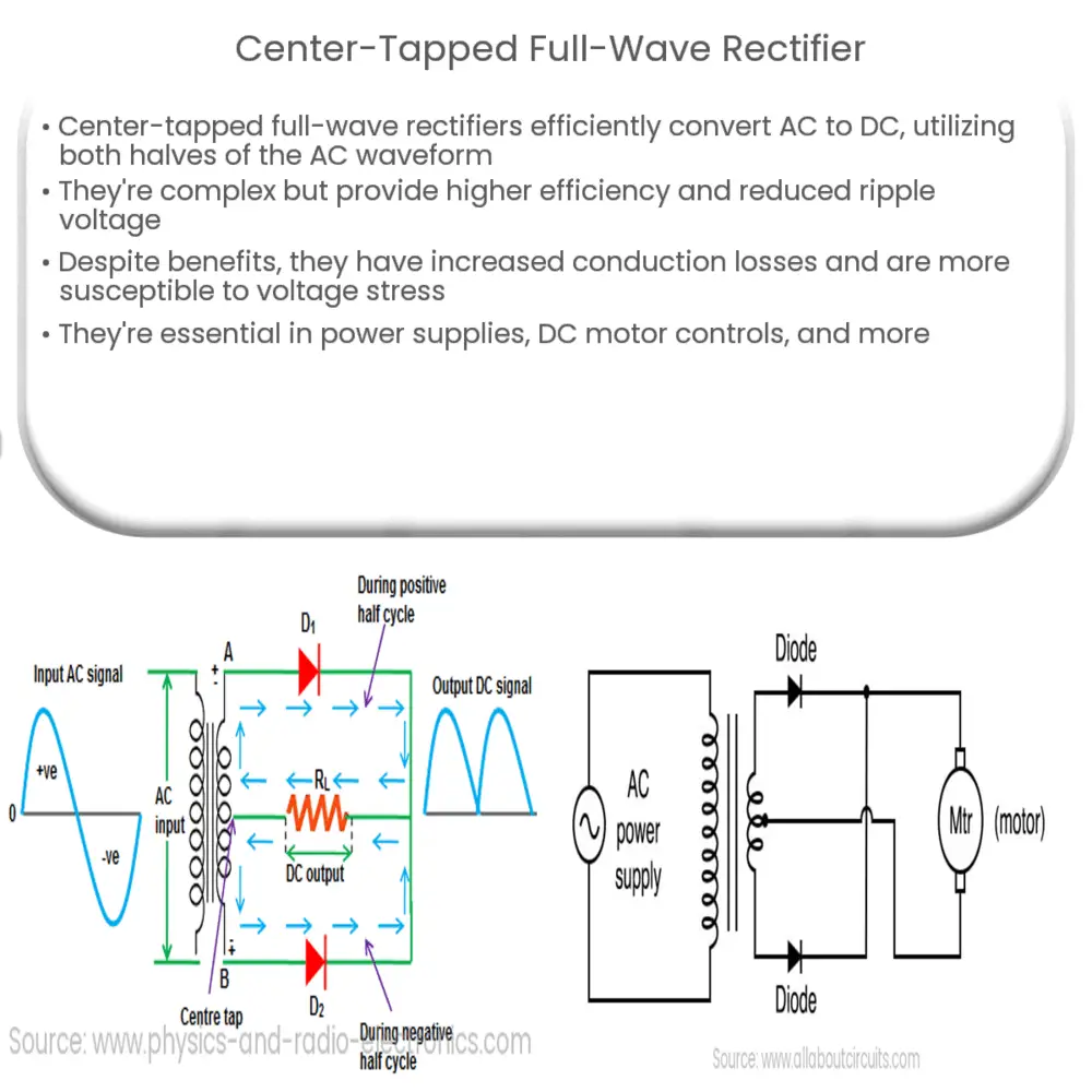
A center-tapped full-wave rectifier works by using a center-tapped transformer and two diodes. The center-tapped transformer has a secondary winding with a center tap, which divides the winding into two equal halves. This center tap is connected to the common ground, effectively splitting the AC waveform into two equal and opposite voltages. The diodes are connected in such a way that they conduct current during different half-cycles of the AC waveform, ensuring that both halves are rectified.
During the positive half-cycle, one diode conducts, while the other is reverse-biased and does not conduct. In the negative half-cycle, the roles are reversed, with the first diode becoming reverse-biased and the second conducting. This process converts the entire AC waveform into a pulsating DC output, with each half-cycle contributing to the output voltage. The resulting output is then filtered to obtain a smooth DC voltage.
Construction
The center-tapped full-wave rectifier consists of the following components:
- Center-Tapped Transformer: This transformer is used to step up or step down the AC input voltage as per the requirements of the rectifier circuit. The center tap on the secondary winding is connected to the common ground, dividing the winding into two equal halves.
- Diodes: Two diodes are used to convert the AC waveform into a pulsating DC output. These diodes are connected in such a way that they conduct during different half-cycles of the AC input, ensuring both halves of the waveform are rectified.
- Load Resistor: The load resistor is connected across the output terminals of the rectifier circuit. The pulsating DC voltage appears across this resistor, and it dissipates the power that is not utilized by the load.
- Filter: A filter, typically a capacitor, is used to smoothen the pulsating DC output and reduce the ripple voltage. This results in a more stable and constant DC voltage across the load resistor.
Applications
Center-tapped full-wave rectifiers find applications in a wide range of power electronics systems, including:
- Power supplies for electronic devices
- Battery charging circuits
- DC motor control systems
- Signal processing and conditioning
In the next part of this article, we will discuss the advantages and disadvantages of center-tapped full-wave rectifiers, as well as compare their performance to other types of rectifier circuits.
Advantages and Disadvantages
Center-tapped full-wave rectifiers offer several advantages over other types of rectifier circuits, but they also come with some drawbacks. Understanding these pros and cons is crucial when deciding on the most suitable rectifier for a specific application.
Advantages
- Higher Efficiency: As both halves of the AC waveform are utilized, center-tapped full-wave rectifiers provide higher efficiency compared to half-wave rectifiers.
- Reduced Ripple Voltage: Due to the use of both half-cycles, the output voltage has a lower ripple factor, resulting in smoother and more stable DC output voltage.
- Smaller Filter Size: The reduced ripple voltage allows for smaller and more cost-effective filter components, which can be advantageous in applications with space constraints or tight budgets.
Disadvantages
- Increased Complexity: The center-tapped full-wave rectifier requires a center-tapped transformer, which can be more complex and expensive than a simple transformer used in other rectifier types.
- Higher Conduction Losses: As only one diode conducts at a time, there are increased conduction losses, which can reduce the overall efficiency of the rectifier.
- Lower Peak Inverse Voltage (PIV) Rating: The diodes in a center-tapped full-wave rectifier have a lower PIV rating compared to a bridge rectifier, making them more susceptible to voltage stress and potential failure.
Comparison to Other Rectifier Circuits
Center-tapped full-wave rectifiers are often compared to bridge rectifiers, another popular type of full-wave rectification circuit. While both rectifiers offer full-wave rectification, they have distinct differences in terms of efficiency, complexity, and PIV ratings.
Bridge rectifiers do not require a center-tapped transformer, which simplifies the circuit design and reduces cost. However, they have higher conduction losses due to two diodes conducting simultaneously during each half-cycle. This results in a higher voltage drop and reduced efficiency compared to center-tapped full-wave rectifiers.
The diodes in a bridge rectifier have a higher PIV rating, making them more robust against voltage stress. This can be an important consideration for applications with high-voltage inputs or rapidly changing load conditions.
Conclusion
Center-tapped full-wave rectifiers are an essential component in power electronics systems, offering efficient conversion of AC to DC voltage while utilizing both halves of the AC waveform. Despite their advantages, they have some drawbacks, including increased complexity and higher conduction losses. When selecting the most suitable rectifier circuit for an application, it is important to carefully consider these factors and weigh them against the requirements and constraints of the specific use case.


