About this website
Electricity and Magnetism simply and easily
This website was founded as a non-profit project, built entirely by a group of young engineers. The entire website is based on our personal perspectives and does not represent any company’s view in the power industry.
The primary purpose of this project is to help the public to learn some exciting and important information about electricity and magnetism.
Enjoy our:
Interactive images
3D diagrams of electrical circuits
Simple calculators
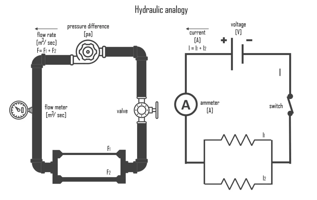
Hydraulic Analogy
The hydraulic analogy, or the electric-fluid analogy, is a widely used analogy between hydraulics and electricity, which is a useful tool for teaching and for those who are struggling to understand how circuits work. it can also be applied to heat transfer problems.
Since electric current is invisible and the processes in play in electronics are often difficult to demonstrate, the various electronic components are represented by hydraulic equivalents. The relationship between voltage and current is defined (in ohmic devices like resistors) by Ohm’s law. Ohm’s Law is analogous to the Hagen–Poiseuille equation, as both are linear models relating flux and potential in their respective systems.
Electricity (as well as heat) was originally understood to be a kind of fluid, and the names of certain electric quantities (such as current) are derived from hydraulic equivalents.
- Voltage is like the pressure difference that pushes water through the hose. It is measured in volts (V). This model assumes that the water is flowing horizontally so that the force of gravity can be ignored.
- Current is equivalent to a hydraulic volume flow rate; that is, the volumetric quantity of flowing water over time. Usually measured in amperes. The wider pipe is, the more water will flow through. It is measured in amps (I or A).
- Electric charge is equivalent to a quantity of water.
- Resistance is like pipe diameter or obstacles in the hose that slow down the water flow. It is measured in ohms (Ω). In hydraulics, resistance is associated with the pressure loss coefficient.
- Batteries can be thought of as water pumps that circulate water through a hose that travels in a closed loop back to the battery. The pump corresponds to the ideal voltage or current source in a DC circuit. The presence of a hydraulic pump is assumed in each of the following descriptions.
- Resistors are comparable to a section of the pipe network where the radius of the pipe is constricted, restricting the rate of fluid flow in that region, the same way that a resistor limits current.
- Wires and their relations to pumps are pretty straightforward, as the copper wire is directly analogous to a water-filled pipe. The resistance of the wire itself is analogous to the drag on the water flowing through a pipe.
- Capacitors are equivalent to a tank with one connection at each end and a membrane dividing the tank in two lengthwise (a hydraulic accumulator). As the pump in the system begins pushing water, the membrane will stretch in response to the pressure from said water. The significance of the stretching is comparable to the amount of charge deposited on a capacitor. It should be fairly easy to see from this description that this membrane’s stretching represents the voltage drop in an electrical circuit, and the discharge of a capacitor is likewise comparable to the membrane returning to its original extent.
- Inductors are equivalent to a heavy paddle wheel placed in the fluid flow. The mass of the wheel and the size of the blades restrict the water’s ability to rapidly change its rate of flow (current) through the wheel due to the effects of inertia, but, given time, a constantly flowing stream will pass mostly unimpeded through the wheel, as it turns at the same speed as the water flow.
- Diodes in the hydraulic analogy compare pretty well to a directional control valve.
- Transistors are like control valves. We can use them to control the flow (ON/OFF), or we can use them to control the flow rate (the current).


